USB Business Card

Overview
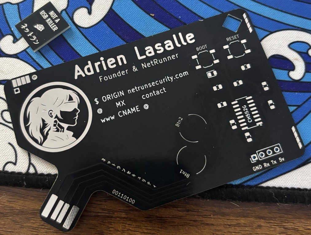
A fully functional USB business card built around the CH552G microcontroller. It looks like a regular business card but plugs directly into any USB-A port, no cable needed. The PCB edge is cut to act as a USB-A male connector.
Under the hood it runs custom firmware, supports USB HID, and has two capacitive touch buttons, a status LED, a UART header for debugging, and a boot/reset button pair for firmware flashing.
NetRunner Card
This is not just a business card. It is a conversation starter, a hacking tool, and a flex all in one.
WARNING - DO NOT PLUG 00110100
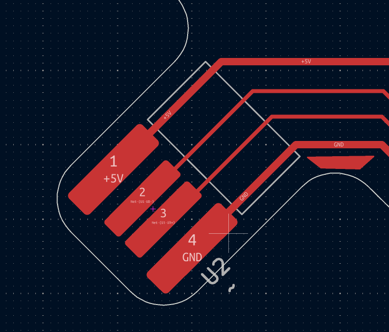
There is a Polarity mistake on the USB Pads of the version 00110100.
If you solder the components of this pcb card and plug it into the computer, you are going to damage your MCU or worst.
The version number is next to the PCB pads, see pictures below.
Version v00110101 fix this issue.
Hardware v00110101
What changed from V2
- Fixed USB pad polarity : V2 had VCC and GND reversed on the edge connector, killing every chip on plug-in.
v00110101has the correct orientation. - Capacitive touch pins corrected : TP2 moved from P3.2 (not a touch pin) to P1.5 (TIN3).
- R6 removed : R6 was creating a voltage divider on the RST pin, putting it in an indeterminate state. RST now pulls cleanly to VCC via R5 only.
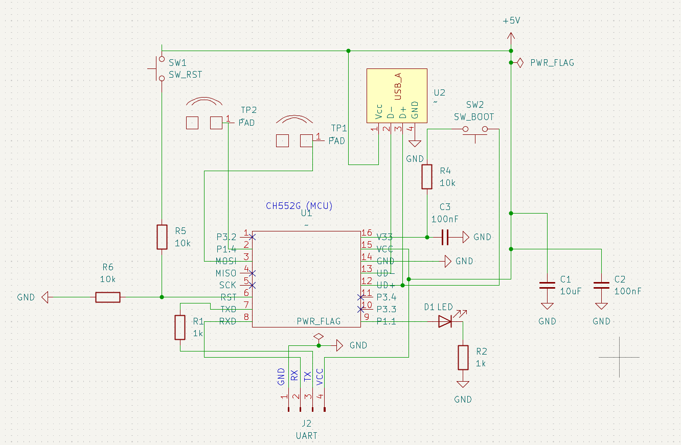
Schematics
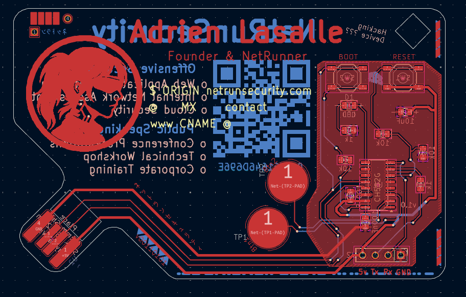
Messy Schematics
This is my first big design, it's a bit messy, I'll try to make it more readable in the futur :)
Key design decisions
Power decoupling:
- C1 (10µF) : bulk reservoir, keeps the chip alive during USB power dips
- C2 (100nF) : high frequency bypass, eliminates switching noise on VCC
- C3 (100nF) : stabilizes the internal 5V to 3.3V LDO on V33
Boot circuit: SW2 connects D+ to V33 through R4 (10k) during power-up, signaling the CH552G to enter bootloader mode for firmware flashing via WCHISP.
Reset circuit: R5 (10k) pulls RST to VCC. SW1 pulls RST to GND when pressed. R6 is intentionally unpopulated, it was causing a 2.5V indeterminate state on the RST line.
Capacitive touch:
- TP1 → P1.4 (TIN2)
- TP2 → P1.5 (TIN3)
Both use the CH552G built-in Touch-Key module. No external components needed. Solder mask is left on top of the pads, the CH552G is sensitive enough to detect through it.
Components
Do not populate R6
Leaving R6 unpopulated is intentional. Installing it creates a voltage divider on RST that prevents the reset button from working correctly.
Pinout
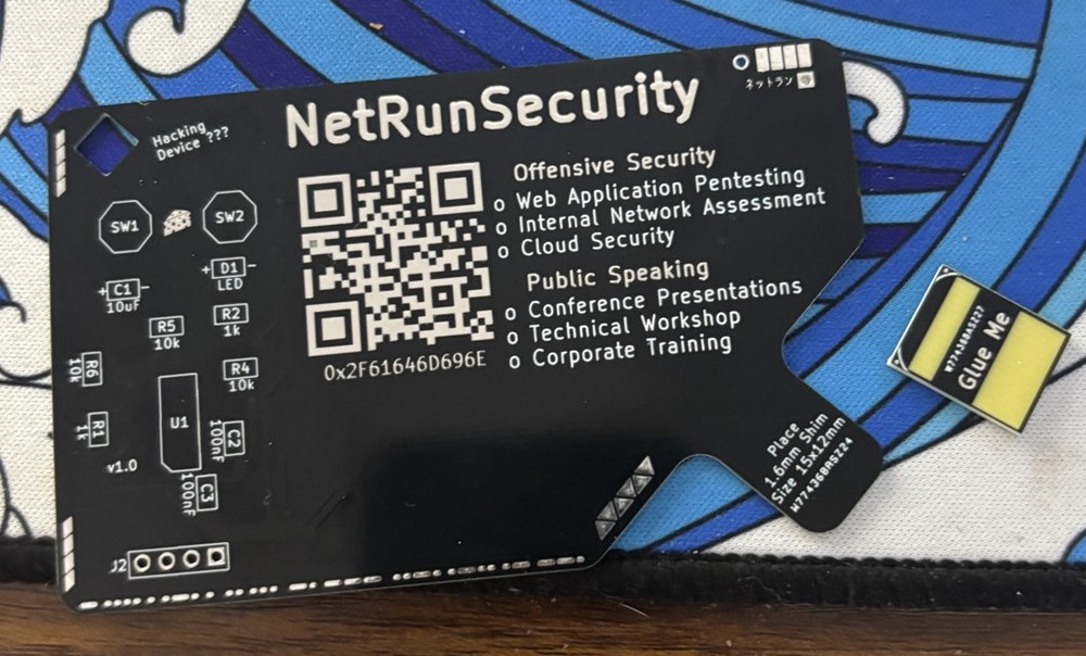
Mechanical PCB Shim
Standard PCB thickness is 1.6mm but a USB-A female socket expects ~2.0mm to 2.5mm insertion thickness for solid contact.
The solution is a custom PCB shim:
- Shim thickness: 1.6mm PCB
- Card thickness: 0.8mm PCB
- Combined: ~2.4mm total, perfect fit for a standard USB-A socket
- Assembly: shim is glued to the back of the card directly under the USB tab area
Firmware
WCHISPTool
Download WCHISPTool from wch-ic.com.
Environment Setup
1. Install Arduino IDE 2.x
Download from arduino.cc/en/software
2. Add ch55xduino board manager
- File → Preferences
- Add this URL to Additional Boards Manager URLs:
https://raw.githubusercontent.com/DeqingSun/ch55xduino/ch55xduino/package_ch55xduino_mcs51_index.json- Tools → Board → Boards Manager
- Search ch55xduino and install
3. Configure board settings
Board         : CH552
Clock Source  : 16 MHz (internal), 3.3V or 5V
Upload method : USB
USB Settings  : USER CODE w/ 148B USB ram
USB Settings
You must select USER CODE w/ 148B USB ram in Tools → USB Settings.
Without this, the HID headers will not be found and compilation will fail.
Flashing Firmware
- Hold SW2 (BOOT)
- Plug card into USB port
- Release SW2 after ~1 second
- Open WCHISPTool, device should enumerate as
VID_4348 PID_55E0 - Click Upload in Arduino IDE
- Unplug and replug to boot into firmware
USB HID Payload - Open Website
This payload runs once on plug-in, blinks the LED 3 times, then opens your website using Win+R on Windows.
Open HidKeyboard example first
Do not create a new empty sketch and paste this code. Open the HidKeyboard example from File → Examples → CH55xDuino → HidKeyboard first. The example folder contains required source files for the HID headers. Then replace the code inside the sketch.
#ifndef USER_USB_RAM
#error "This example needs to be compiled with a USER USB setting"
#endif

#include "src/userUsbHidKeyboard/USBHIDKeyboard.h"

#define LED_PIN 33  // P1.1

void setup() {
  USBInit();
  pinMode(LED_PIN, OUTPUT);

  // Startup signal — 3 blinks
  for (int i = 0; i < 3; i++) {
    digitalWrite(LED_PIN, HIGH);
    delay(200);
    digitalWrite(LED_PIN, LOW);
    delay(200);
  }

  delay(2000); // Wait for HID to be recognized by the PC

  // Win + R to open Run dialog
  Keyboard_press(KEY_LEFT_GUI);
  Keyboard_press('r');
  delay(100);
  Keyboard_releaseAll();
  delay(500);

  // Type the URL
  Keyboard_print("https://www.netrunsecurity.com/");
  delay(200);

  // Enter
  Keyboard_press(KEY_RETURN);
  delay(100);
  Keyboard_releaseAll();

  // LED stays on = payload sent
  digitalWrite(LED_PIN, HIGH);
}

void loop() {
  // One-shot payload, nothing to do here
}
TouchPad Testing
This example uses the touchpads capabilities and should make the LED blink once you touch the pads.
#include <TouchKey.h>

#define LED_PIN   11    // P1.1
#define TP1_BIT   (1 << 2)
#define TP2_BIT   (1 << 3)
#define BOTH_BITS (TP1_BIT | TP2_BIT)

void setup() {
  pinMode(LED_PIN, OUTPUT);
  digitalWrite(LED_PIN, LOW);

  TouchKey_begin(BOTH_BITS);

  // 2 quick blinks = ready
  for (uint8_t i = 0; i < 2; i++) {
    digitalWrite(LED_PIN, HIGH); delay(100);
    digitalWrite(LED_PIN, LOW);  delay(100);
  }
}

void loop() {
  TouchKey_Process();
  uint8_t touched = TouchKey_Get();

  uint8_t t1 = (touched & TP1_BIT) ? 1 : 0;
  uint8_t t2 = (touched & TP2_BIT) ? 1 : 0;

  if (t1 && t2) {
    // Both: fast blink
    digitalWrite(LED_PIN, HIGH); delay(50);
    digitalWrite(LED_PIN, LOW);  delay(50);
  } else if (t1 || t2) {
    // Either one: solid on
    digitalWrite(LED_PIN, HIGH);
  } else {
    // None: off
    digitalWrite(LED_PIN, LOW);
  }

  delay(20);
}
Troubleshooting The Hard Way
Post-mortem
Two CH552G chips were sacrificed during development of V2. Here is what went wrong.
ERR_01 : Reversed USB polarity
Every chip burned within seconds of plug-in. Cold multimeter checks showed no shorts (OL on all rails). USB power meter showed 3.7A on plug-in, a catastrophic short. Root cause: USB edge connector pads were in the wrong order. VCC was touching the GND contact of the USB socket and vice versa. Fix: corrected pad orientation in KiCad for v00110101.
Lessons Learned
- Always verify USB edge connector pad polarity before ordering
- A USB power meter is a mandatory tool for first power-up of any custom USB board
- Cold resistance checks (OL) do not catch reversed polarity, always verify orientation physically
- CH552G Touch-Key works through solder mask, no need to expose copper pads
- A custom PCB shim is cleaner and more reliable than a paper shim for USB edge connectors